AxisVM
  • Products
    • AXISVM
    • AXISVM X7 New Features
    • AXISVM Modules
    • Configurations
    • AXISVM Rapido
    • Free Products
    • HW/SW requirements
  • Downloads
    • Free Trial Versions
    • AXISVM Education Version
    • X7 Installation Package
    • Free Downloads
    • Latest Release Updates
    • Sentinel Driver
    • Applications & Plugins
  • Request for Quotation
  • References
    • AXISVM Testimonials
    • Customer Projects
    • Showcases
    • Recommendations
    • Art of Modeling
  • Support
    • Knowledge Base
    • Customer Support
    • Training Materials, Guides
    • Verification Examples
    • Patch Tests
    • HW/SW requirements
  • Contact
    • About us
    • Partners
  • HUN
  • DE

Latest articles

  • Increments and iterations
  • Convergence criterias
  • Modifying domains
  • Basics of vibration and seismic analysis
  • Grasshopper installation guide
  • Removal of unnecessary elements
  • Creation of a simple model using AxisVM COM server

Installation & Licencing

  • Setting up the COM server using Python
  • Setting up the COM server using Visual Studio
  • Error code 70 – Sentinel SuperPro-NET key
  • AxisVM-Autodesk Revit interface does not appear in Revit
  • Error when installing update package – errorcode 5
  • Error code -115
  • Save and restore settings

General

  • Parameter is incorrect – AxisVM does not start
  • Coordinate Systems
  • AXS files are not recognized by Windows 10
  • Access violation in module atio6axx.dll error message
  • Program can’t start due to spro_aex64.dll error message
  • Shear cross-section area Ay/Az

Modeling

  • Modifying domains
  • Removal of unnecessary elements
  • Creation of a simple model using AxisVM COM server
  • Compression or tension-only line elements
  • Scissor joint

Loads

  • Filter out critical load combinations
  • Auto-generated wind load differs from standard values
  • List of AxisVM messages – Loads
  • Number of automatic loadcombinations

Analysis & Results

  • Increments and iterations
  • Convergence of non linear calculations
  • Signs of internal forces
  • Newton-Raphson iteration for SDOF and MDOF systems
  • Convergence criterias
  • List of AxisVM messages – Analysis 
  • FOOTFALL ANALYSIS GUIDE
  • Simultaneous internal forces for connection design
  • The model contains singularities, unstable mode
  • Smoothing of results on beam and rib elements
  • Mathematical relative calculation errors
  • No convergence after nonlinear analysis

Vibration & Earthquake

  • Basics of vibration and seismic analysis
  • Modal response spectrum analysis mass participation can’t reach 90%

Design

  • Simply supported timber beam deflection check in module TD1
  • Buckling coefficients in Design calculation differs from Design parameters setting
  • List of AxisVM messages – RC design
  • X-LAM GUIDE – Structural Description of X-LAM Members
  • Critical results for concrete columns
  • AUTO Mcr GUIDE
  • APPLICATION OF STEEL CONNECTION (SC1 MODULE)
  • AutoNcr FLEXURAL BUCKLING COEFFICIENT CALCULATION (Guide)
  • Reducing the time of the design process

Reinforcement

  • Actual reinforcement rendering on the 3D model view

Documentation

  • Options for editing drawings of report maker

Elements

  • Compression or tension-only line elements

BIM Connections

  • Modeling doubly curved surfaces
  • Grasshopper installation guide
  • IFC connection

Mesh generation

  • Generating mesh for surface elements

AXISVM API

  • Grasshopper installation guide
  • Creation of a simple model using AxisVM COM server
  • Home
  • BIM Connections
  • Modeling doubly curved surfaces

Modeling doubly curved surfaces

Table of Contents
  • Problem/Question
  • Explanation/Solution
    • Triangular mesh
    • Traditional - Domains
    • Advanced - finite element areas directly
  • Conclusion

Problem/Question #

Can we model doubly curved surfaces using the AxisVM program?

In the program, the finite element method’s specific properties make defining a domain for curved surfaces impossible. The condition for defining a domain is that all its points are in one plane.

Explanation/Solution #

As it has been said, we cannot directly define such surfaces; we must use a certain kind of approximation in AxisVM to model such a structure. The first input condition for this is that we need a triangular mesh.

Triangular mesh #

We need the triangular mesh because the triangle is the simplest form in which, no matter how they stand, they will always designate a plane from the 3D space. Of course, by changing the size of the triangles, we can approximate our desired curved surface more and more, thus clarifying the results.

We can get this mesh from:

  • Given by the contractor, other disciplines (architectural, e.g.)
  • Manually (in an external program)
  • Parametrically (in an external program)

Of course, the most favorable option is to produce the network parametrically. In this way, the size of the triangulation can also be easily changed, which can increase the accuracy of the approximation. A program that can be used for this is the Rhino/Grasshopper pair, from where it can be perfectly transferred to AxisVM, any triangular network of any kind. And after importing the triangle mesh, we can define domains directly.

The network, of course, can be a . dxf import also or any kind of drawing file. Creating such a network of lines within the program is technically possible, but this is strongly not recommended. The next step is creating domains/interfaces if we have the network. Since there are two ways to proceed and only one is recommended in such a case, they will be discussed further.

Traditional – Domains #

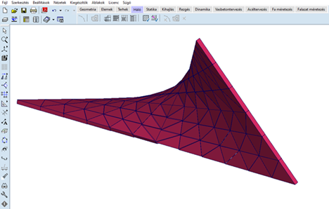
In the traditional way, you create domains. This way, the program automatically meshes the surfaces according to the set parameters. This is not the best solution for curved surfaces where we work from a triangular mesh.

Advanced – finite element areas directly #

The program has an option that can be turned on, with which extra buttons appear on the toolbar. With these extra functions, we can skip the domain “level” and directly define a finite element area with the given properties.  These areas will not be meshed later by the software.

The switch for these buttons can be found at:


The functions that appear in the ‘Geometry’ and ‘Elements’ tabs are:


With the right-most function in the first image, we can find the enclosed surfaces (triangles, in our case) and make the software recognize them as areas for finite elements. Then, in the second image, we can set properties directly for these finite element areas.

Conclusion #

It can be said that it is possible to model curved surfaces, but for this to go smoothly and quickly, we will always need an external source. This is better for a parametric, dynamic connection to an external program such as Grasshopper, or it can be an imported drawing file.

It is important that triangulation should not be refined by defining domains on the triangular areas and then meshing them with smaller finite element mesh. The inner nodes of the FEM mesh will not be placed on the curved surface but formed in the plane of the triangles. Thus, the finite-element mesh will no longer be a model of the original, curved surface but of a surface consisting of flat “sheets” touching the original surface. The triangles meshed in their plane will be softer than the edges, so they will have local problems.

Still stuck? How can we help?

How can we help?

Grasshopper installation guide
Table of Contents
  • Problem/Question
  • Explanation/Solution
    • Triangular mesh
    • Traditional - Domains
    • Advanced - finite element areas directly
  • Conclusion

CONTACT

InterCAD

Software Development Company
42 Rákóczi út, Floor V.
Budapest, H-1072
Hungary, EU

 
PHONE:    +36 (1) 322-9072
FAX:           +36 (1) 322-6668
SALES:      
SUPPORT:

NEWSLETTER

I consent to AxisVM sending me newsletters and informing me about product updates and discounts


    FOLLOW US

    Facebook-f Linkedin Youtube Instagram

    SOURCES OF PHOTOS USED ON THE WEBSITE >>

    IMPRESSUM >>

    © Copyright 2023 | Inter-CAD Kft. – All rights reserved

    We are using cookies to give you the best experience on our website.

    You can find out more about which cookies we are using or switch them off in settings.

    AxisVM
    Powered by  GDPR Cookie Compliance
    Privacy Overview

    This website uses cookies so that we can provide you with the best user experience possible. Cookie information is stored in your browser and performs functions such as recognising you when you return to our website and helping our team to understand which sections of the website you find most interesting and useful.

    Strictly Necessary Cookies

    Strictly Necessary Cookie should be enabled at all times so that we can save your preferences for cookie settings.

    If you disable this cookie, we will not be able to save your preferences. This means that every time you visit this website you will need to enable or disable cookies again.

    Cookie Policy

    More information about our Cookie Policy