- Create a new Model and store it in a variable.
- Change the unit system and the national design code.
- Define nodes and a line.
- Define the material and the cross-section.
- Define the line as a beam.
- Define the supports.
- Define self-weight and distributed load.
- The created beam.
- Save the model.
- Run the analysis.
- Retrieve the results after analysis.
- Change the view of the model
- Error Handling.
This article will show the steps to build a simply supported beam model using AXISVM COM server using C# programming language and Visual studio. The COM server can be used to create models, run analyses and retrieve results from AXISVM. Here, C# is used as an example; other programming languages can be used in the same manner. This article will not cover the steps to set up the COM server. Steps of setting up the COM server are described in the following articles:
Setting up the COM server using Visual Studio
Setting up the COM server using Python
A simple Windows Form application is created to get the beam dimensions and load magnitude from the user, create a simply supported beam and run the analysis in AXISVM. Finally, show and save the results, including the reactions, displacements, forces and stresses, as shown in the image below.

The COM server Reference Guide provides a full description of all the functions that will be used to create the model, run the analysis and retrieve the results. It clearly shows how to use each function and the appropriate parameters that must be passed in order to apply each function successfully. Therefore, it will be referenced here frequently. The Reference Guide shows all the interfaces that are available in the COM server. The main interface is IAxisVMApplication. For each interface, the Reference Guide lists all the available enums, functions, structs and properties that can be used to access data or perform actions. The available interfaces start with IAxisVM, but the implemented objects are accessed without it (e.g., IAxisVMModels is axisVMApplication.Models).
Create a new Model and store it in a variable. #
After creating an object of AxisVMApplication, as shown in the previous article, the Models interface can be used to get the currently open model or to create a new model in AXISVM. The Reference Guide shows that IAxisVMModels has a function called New() that can be used to create a new model or the property item[int index] that can be used to get the open model. As shown in the code snippet below, line 1 creates a new model, and line 2 gets the created model and stores it in a variable called model.
					axisVMApplication.Models.New();                         // Create a new model.
IAxisVMModel model = axisVMApplication.Models.Item[1];  // store it in model variable.
Change the unit system and the national design code. #
The next step is to change the unit system and national design code. To change the unit system, the function ChangeUnitSystem(string Name) of IAxisVMApplication can be used. The available unit systems are listed in the Reference Guide. Line 1 in the code snippet below changes the unit system to EU units. The design code can be changed using the property model.Settings.NationalDesignCode of IAxisVMSettings interface. The Reference Guide shows the property type that must be provided on the left side of the property name, as shown in the image below. For the NationalDesignCode property, the provided property must be of the type ENationalDesignCode, as shown in the image below. Line 2 of the code snippet sets the NationalDesignCode to the Eurocode.
					int unitId = axisVMApplication.ChangeUnitSystem("eu");               //Change unit system.
model.Settings.NationalDesignCode = ENationalDesignCode.ndcEuroCode; // Change code.

Define nodes and a line. #
The next step is to define two nodes and one line element that connects the two nodes. To define the nodes, the function, Add ([in] double x, [in] double y, [in] double z) of the interface IAxisVMNodes must be called with the XYZ coordinates of the node. The Reference Guide shows that the function will return the node index, as shown below.

- Line 1 in the code snippet adds one node at (x=0, y=0, z=0), and line 2 adds another at (x=beamLength, y=0, z=0). Line 3 adds a line element that connects the two nodes. This can be done using the function Add ([in] long StartNode, [in] long EndNode, [in] ELineGeomType GeomType, [i/o] RLineGeomData GeomData) of IAxisVMLines interface. As shown in the image below, the first and the second parameters are the indices of the first and second nodes, respectively. The third parameter is an enum of type ELineGeomType, which determines the type of the line; straight or circleArc. The fourth parameter is a struct of type RLineGeomData; it is used for circleArc lines, which is not relevant here. The function would return the index of added line or error code if it were not successful.
					int node1Id = model.Nodes.Add(0, 0, 0);               // Add first Node
int node2Id = model.Nodes.Add(beamLength, 0, 0);      // Add second node
int lineId = model.Lines.Add(node1Id, node2Id, ELineGeomType.lgtStraightLine, ref rLineGeomData); // Add line.

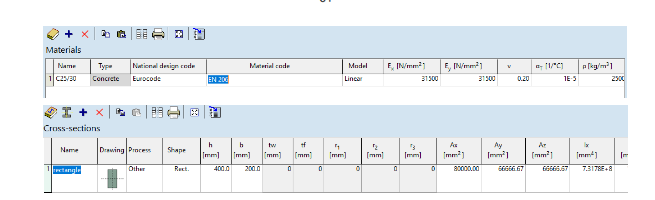
Define the material and the cross-section. #
The IAxisVMMaterials interface provides several functions to define materials, including AddDialog, AddFromCatalog, AddFromCatalogFile and others. In this example, the function AddFromCatalog is used to add material using the available materials in AXISVM, where the first parameter is the NationalDesignCode and the second parameter is the MaterialName provided as a string. The exact material name must be provided as shown in the AXISVM materials library. Here, as an example, concrete C25/30 of the Eurocode is used. The first line of the code snippet below shows the material definition. The method returns the material index if adding the material was successful. Similar to IAxisVMMaterials, IAxisVMCrossSections provides several methods to define cross sections, such as AddFromDialog, AddFromEditor and functions provided specifically to define special sections. Here, the AddRectangular function is used to define a rectangular cross-section. As shown in the image below, the first parameter is a unique name for the cross-section, the second is the width, the third is the height, and the fourth is ECrossSectionProcess for steel sections, which is not relevant in this example. The second line of the code snippet adds a rectangular section to the CrossSections interface of AXISVM. If successful, the function returns the index of the added section. The images below show the added material and cross-section to AXISVM.
					int materialId = model.Materials.AddFromCatalog(ENationalDesignCode.ndcEuroCode, "C25/30");  //Define Material
int crossSectionId = model.CrossSections.AddRectangular("rectangle", width, height, ECrossSectionProcess.cspOther);   //Define Cross-Section


Define the line as a beam. #
After defining both the material and the cross-section, the line element can be defined as a beam by using the function DefineAsBeam of the IAxisVMLine interface. The first line of the code snippet gets the previously defined line element by the Item[int index] property of the IAxisVMLines interface and stores it in the axisVMLine variable. The second line uses the DefineAsBeam function to define the beam using the material Id, the cross-section Id and the eccentricity points of struct RPoint3d. The eccentricity points must be passed by reference.
					IAxisVMLine axisVMLine = model.Lines.Item[lineId];
int beamId = axisVMLine.DefineAsBeam(materialId, crossSectionId, crossSectionId, ref startEndEccentricity, ref startEndEccentricity);

Define the supports. #
The nodal supports can be defined using AddNodalGlobal_V153 of IAxisVMNodalSupports. As shown below, the function requires two arguments; the NodalSupportSpringParameters of type RNodalSupportSpringParams and the NodeId of type int. The RNodalSupportSpringParams is a struct which contains another struct of type RSpringParamIndexes. The indices of springs must be provided to RSpringParamIndexes to define supports in the XYZ directions. Springs are defined as either translation or rotation springs. Therefore, to define supports, a new instance of RNodalSupportSpringParams must be defined as shown by line 2 of the code snippet and the SpringParamIndexes in (x, y, z, xx, yy and zz) direction must be defined with the appropriate spring indcies. The default Rigid-Translation and Rigid-Rotation of AxisVM can be retrieved using model.SpringParams.IndexOfName(springName) with the appropriate spring name as shown in lines 3-4. Finally, the support can be added using AddNodalGlobal_V153, as shown in line 5.
					AxisVMNodalSupports axisVMNodalSupports = model.NodalSupports;
RNodalSupportSpringParams rNodalSupportSpring1 = new RNodalSupportSpringParams();
rNodalSupportSpring1.SpringParamIndexes.x = model.SpringParams.IndexOfName("Rigid - Translational");
rNodalSupportSpring1.SpringParamIndexes.yy = model.SpringParams.IndexOfName("Soft - Rotational");
int nodeSupport1 = axisVMNodalSupports.AddNodalGlobal_V153(ref rNodalSupportSpring2, node1Id);

Define self-weight and distributed load. #
The self-weight can be defined using AddBeamSelfWeight of IAxisVMLoads, as shown in line 2 below. The function requires two parameters the LineId defining the beam and the LoadCaseId, which is equal to 1 for the first loadCase. Several types of load can be defined using the IAxisVMLoads interface, such as AddBeamConcentrated, AddBeamDistributed, AddBeamStress, or AddBeamThermal. As an example, the AddBeamDistributed is used here to define a distributed load acting on the beam. As shown by the image below, AddBeamDistributed requires one parameter of type RLoadBeamDistributed, which is a struct. Therefore, a new instance must be declared as shown by line 4, and the properties of the distributed load must be assigned as shown in lines 5-12, including the DistributionType, LoadCaseID and LineID. qx1, qy1, qz1, qx2, qy2, qz2 are the magnitudes of the distributed load in x y z directions for the first and second points, respectively. Position1 and Position2 are the locations of the first and second points, respectively. The Reference Guide provides a full description of all the properties included in the struct to define the load. Finally, the defined RLoadBeamDistributed must be passed to the function to add the distributed load. If the load is added successfully, the function returns the load index.
					// Adding the Self weight.
int selfWeight=axisVMLoads.AddBeamSelfWeight(lineId, LoadCaseId);
// Define distributed load
RLoadBeamDistributed rLoadBeam = new RLoadBeamDistributed(); //define new RLoadBeamDistributed
rLoadBeam.DistributionType = EBeamRibDistributionType.brdtLength; //distributed by length or projected
rLoadBeam.LoadCaseId = loadCaseId;                          // Load case ID
rLoadBeam.LineId = beamId;                                  // Beam ID
rLoadBeam.qz1 = -distributedLoad;                           // Magnitude of the load - first point
rLoadBeam.qz2 = -distributedLoad;                           // Magnitude of the load - second point
rLoadBeam.Position1 = 0;                                    // Position of the load - first point
rLoadBeam.Position2 = length;                               // Position of the load - second point
rLoadBeam.SystemGLR = ESystem.sysGlobal;                    // coordinate system of load components
// Adding the distributed load to the beam.
int loadId = axisVMLoads.AddBeamDistributed(rLoadBeam);     // Adding the distributed load to the beam.

The created beam. #
The images below show the final product of applying all the previously mentioned functions using the COM interface.


Save the model. #
Before running the analysis, it is important to save the model. Therefore, the function SaveToFile of IAxisVMModel can be used to save the model. The first parameter of the function is the FileName, which is the name of the saved file, and the second parameter is SaveResults of type ELongBoolean, indicating whether the currently available results are saved or not.
ELongBoolean modelSaveStatus = model.SaveToFile("model1", ELongBoolean.lbTrue); //save to file.

Run the analysis. #
The IAxisVMCalculation interface allows running several types of analyses, such as linear analysis, non-linear analysis, buckling analysis, vibration analysis and others. Here, the function LinearAnalysis2 is used to run a linear analysis. As shown by the image below, the function takes three parameters; the first is of type ECalculationUserInteraction to indicate whether the user should interact with AxisVM during the analysis to respond to warning messages. The second is of type ELongBoolean to show error messages in AxisVM. The third parameter is ErrorList of type string, and it must be passed by out keyword to receive the errors, if any, after the function is performed. The code snippet below shows how the parameters can be passed to the function. The function will return ElongBoolean.lbTrue if the analysis was completed.
					String errorList;     // Define string variable.
ELongBoolean analysisStatus = model.Calculation.LinearAnalysis2(ECalculationUserInteraction.cuiNoUserInteractionWithAutoCorrect, ELongBoolean.lbTrue, out errorList);

Retrieve the results after analysis. #
The interface IAxisVMResults provides various functions to retrieve the results of the analysis. The interface includes results for displacements, forces, stresses, reinforcement calculations, steel design and others. Inside the IAxisVMResults interface, there are interfaces for displacements, forces, and stresses with IAxisVMDisplacements, IAxisVMForces and IAxisVMStresses. These interfaces contain several functions and properties to extract the results from the AxisVM database. As an example, IAxisVMDisplacements can be used to extract the beam displacements using GetMemberDisplacementsByLoadCaseId. Several parameters must be passed to the function as shown by the image below, including MemberID, LoadCaseID, LoadLevelOrModeShapeOrTimeStep, the Analysistype of EAnalysisType, WithReinforcement of type ELongBoolean and two arrays passed with out keyword for displacements and PosX of type RDisplacementValues and double, respectively. The LoadLevelOrModeShapeOrTimeStep is used for other analysis types, such as nonlinear analysis or buckling analysis. For linear analysis, it is equal to 1. The two arrays passed with out keyword will be filled with the displacement results. The arrays can be defined and initialized using the C# Array.CreateInstance(Type type ,int32 dimension) function, as shown by lines 1-2 in the code snippet below. The function GetMemberDisplacementsByLoadCaseId will return the number of cross-sections along the length of the beam. The displacements array will contain the same number of objects RDisplacementValues as the number of cross-sections returned. The objects contain the components of deformation at each cross-section. The PosX array will contain the locations of the cross-sections along the length of the beam. The arrays start with index 1. Similar functions can be used to get forces and stresses using Forces.GetMemberForcesByLoadCaseId and Stresses.GetMemberStressesByLoadCaseId.
					Array displacementResults = Array.CreateInstance(typeof(RDisplacementValues), 1); //Define array of type RDisplacementValues
Array crossSectionPositionsDisplacement = Array.CreateInstance(typeof(double), 1); //Define array of type double
int displacementResultStatus = model.Results.Displacements.GetMemberDisplacementsByLoadCaseId(beamId, loadCaseId, loadLevel, EAnalysisType.atLinearStatic, ELongBoolean.lbFalse, out displacementResults, out crossSectionPositionsDisplacement);

Array forcesResults = Array.CreateInstance(typeof(RLineForceValues), 1);
Array crossSectionPositionsForces = Array.CreateInstance(typeof(double), 1);
int forcesResultStatus = model.Results.Forces.GetMemberForcesByLoadCaseId(beamId, loadCaseId, loadLevel, EAnalysisType.atLinearStatic, out forcesResults, out crossSectionPositionsForces);

Array stressResults = Array.CreateInstance(typeof(RLineStressValues), 1);
Array crossSectionPositionsStress = Array.CreateInstance(typeof(double), 1);
int stressResultStatus = model.Results.Stresses.GetMemberStressesByLoadCaseId(beamId, loadCaseId, loadLevel, EAnalysisType.atLinearStatic, out stressResults, out crossSectionPositionsStress);

The obtained results can be displayed in the program as was shown previously or saved to a result file as shown below.

Change the view of the model #
The View property of IAxisVMModel can be used to adjust the view in AxisVM, where EView.vFront corresponds to the X-Z direction, as shown by the Reference Guide. The function FitInView() of IAxisVMModel can be used to fit the model in view, as shown by the code snippet below.
					model.View = EView.vFront;        // Change view to X-Z.
model.FitInView();                // Fit in view.
Error Handling. #
All the interfaces have a special enum containing the list of error codes and their meanings that can be received during performing the functions. For example, the IAxisVMDisplacements interface contains an EDisplacementError enum that has all the possible errors that can be received if GetMemberDisplacementsByLoadCaseId is applied. The C# function Enum.GetName(Type, Object) can be used to get the name of each error code, as shown below.
Enum.GetName(typeof(EDisplacementError), errorCode); // Get the name of the Enum.
The full project can be downloaded here.