Problem description #
When using the automatic wind load generation option in AxisVM, the generated zones and loads may differ slightly from the EuroCode regulations.
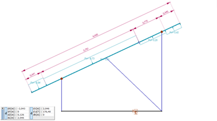
For example, consider a free-standing semi-sloping roof. The following table shows the standard values of the wind pressure factors and the location of these zones.

Example of the location of wind load zones generated in AxisVM for a mono-pitch canopy under lateral wind load:
Reason #
When generating wind loads in AxisVM, the program considers the global pressure coefficient and the resulting wind load action point for the whole structure, specified separately in the standard and the factors for each zone in Table 7.6.
The latter, according to the standard, is located at the quarter of the roof line, which is shown in the following figure:
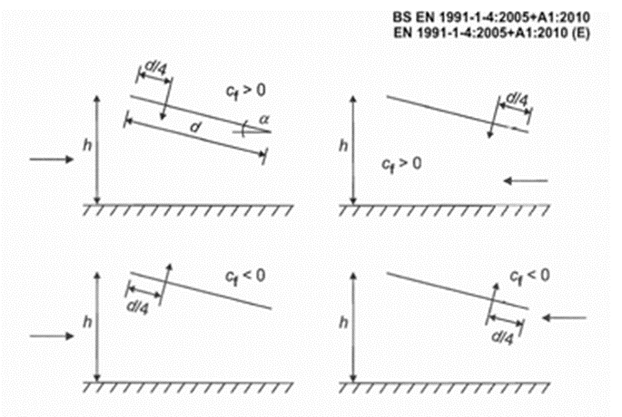
To meet these requirements, the program uses the zones (Table 7.6) as a starting point but may differ from them.
Zone A is split into two parts, A1 and A2, to help ensure that the location of the resultant force is correct.
Zone B is neglected, which would result in a more complicated load distribution.
Conclusion #
The mentioned method above results that the module considering the resultant (global) wind load and its point of action as fixed, but at each zone, the wind load could differ from the maximum and minimum value in some special cases (like mono-pitched canopy roof).
If necessary, the elements that directly support the roof (load panel) should be checked separately for the maximum or minimum wind loads.