AxisVM
  • Products
    • AXISVM
    • AXISVM X7 New Features
    • AXISVM Modules
    • Configurations
    • AXISVM Rapido
    • Free Products
    • HW/SW requirements
  • Downloads
    • Free Trial Versions
    • AXISVM Education Version
    • X7 Installation Package
    • Free Downloads
    • Latest Release Updates
    • Sentinel Driver
    • Applications & Plugins
  • Request for Quotation
  • References
    • AXISVM Testimonials
    • Customer Projects
    • Showcases
    • Recommendations
    • Art of Modeling
  • Support
    • Knowledge Base
    • Customer Support
    • Training Materials, Guides
    • Verification Examples
    • Patch Tests
    • HW/SW requirements
  • Contact
    • About us
    • Partners
  • HUN
  • DE

Latest articles

  • Increments and iterations
  • Convergence criterias
  • Modifying domains
  • Basics of vibration and seismic analysis
  • Grasshopper installation guide
  • Removal of unnecessary elements
  • Creation of a simple model using AxisVM COM server

Installation & Licencing

  • Setting up the COM server using Python
  • Setting up the COM server using Visual Studio
  • Error code 70 – Sentinel SuperPro-NET key
  • AxisVM-Autodesk Revit interface does not appear in Revit
  • Error when installing update package – errorcode 5
  • Error code -115
  • Save and restore settings

General

  • Parameter is incorrect – AxisVM does not start
  • Coordinate Systems
  • AXS files are not recognized by Windows 10
  • Access violation in module atio6axx.dll error message
  • Program can’t start due to spro_aex64.dll error message
  • Shear cross-section area Ay/Az

Modeling

  • Modifying domains
  • Removal of unnecessary elements
  • Creation of a simple model using AxisVM COM server
  • Compression or tension-only line elements
  • Scissor joint

Loads

  • Filter out critical load combinations
  • Auto-generated wind load differs from standard values
  • List of AxisVM messages – Loads
  • Number of automatic loadcombinations

Analysis & Results

  • Increments and iterations
  • Convergence of non linear calculations
  • Signs of internal forces
  • Newton-Raphson iteration for SDOF and MDOF systems
  • Convergence criterias
  • List of AxisVM messages – Analysis 
  • FOOTFALL ANALYSIS GUIDE
  • Simultaneous internal forces for connection design
  • The model contains singularities, unstable mode
  • Smoothing of results on beam and rib elements
  • Mathematical relative calculation errors
  • No convergence after nonlinear analysis

Vibration & Earthquake

  • Basics of vibration and seismic analysis
  • Modal response spectrum analysis mass participation can’t reach 90%

Design

  • Simply supported timber beam deflection check in module TD1
  • Buckling coefficients in Design calculation differs from Design parameters setting
  • List of AxisVM messages – RC design
  • X-LAM GUIDE – Structural Description of X-LAM Members
  • Critical results for concrete columns
  • AUTO Mcr GUIDE
  • APPLICATION OF STEEL CONNECTION (SC1 MODULE)
  • AutoNcr FLEXURAL BUCKLING COEFFICIENT CALCULATION (Guide)
  • Reducing the time of the design process

Reinforcement

  • Actual reinforcement rendering on the 3D model view

Documentation

  • Options for editing drawings of report maker

Elements

  • Compression or tension-only line elements

BIM Connections

  • Modeling doubly curved surfaces
  • Grasshopper installation guide
  • IFC connection

Mesh generation

  • Generating mesh for surface elements

AXISVM API

  • Grasshopper installation guide
  • Creation of a simple model using AxisVM COM server
  • Home
  • BIM Connections
  • IFC connection

IFC connection

Table of Contents
  • AxisVM IMPORT
  • STATICAL MODEL
    • AUTOMATIC GENERATION
    • ASSIGNING OBJECTS' PROPERTIES MANUALLY
  • POST-IMPORT MODIFICATIONS
    • WALL/SLAB CONNECTION
    • DETAIL LEVEL & MODEL SIMPLIFICATIONS
    • CORNERS BETWEEN WALLS
    • OVERLAPPING SLABS
    • NON-STRUCTURAL ELEMENTS
    • COMPLEMENTING THE MODEL

The Industry Foundation Classes (IFC) is an open standard in construction for the digital description of building models. It is also referred to as BIM (Building Information Modelling).

Logical building structures (e.g., walls, slabs, openings) and their related properties (e.g., material, component strength) are mapped. With the help of IFC files, complex spatial planning data can be transferred between different software systems.

IFC is supported by numerous software for the exchange of building data. Its application areas are, among many others, 2d/3d CAD, static and energy analysis, and determination of quantities or costs.

AxisVM IMPORT #

AxisVM supports the import/export of IFC files from versions 2.0 through 2×4 (current Version, also referred to as IFC4). IFC files can be imported through the menu File / Import.

In case the IFC file is not shown, the file type must be changed (selection  menu at the bottom of the window).

In import dialogue, several options can be chosen.

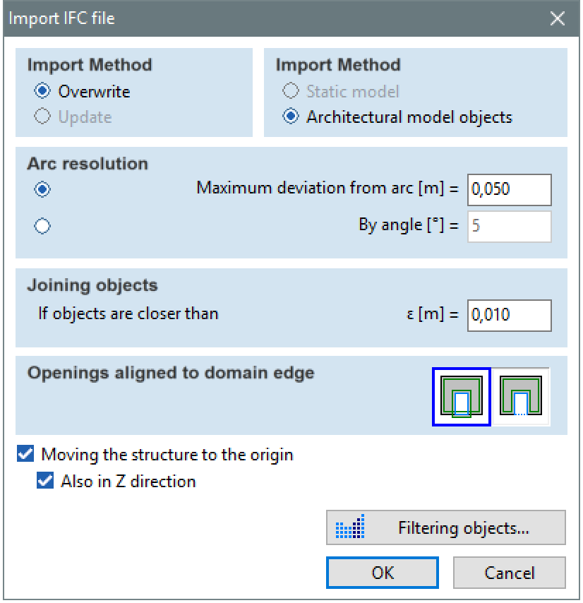
If an IFC model is already imported into the current model, it is possible to update it to readjust changes. The modifications are documented in an additional window.

Automatic detection of changes: This function lists new, modified and deleted objects when reimporting IFC files. Each change can be approved or ignored. Selecting a difference in the tree, shows the selected element’s position within the current model.


Filtering objects: the user can select elements according to different criteria.

Files with format IFC 2×4 (current version) can contain the definition of loads, supports and joints, as well as other structural elements. In this case, the option „Static model“ at Import Method is available for reading the file.

After importing the file, the architectural model will be visible in AxisVM.

The individual components are colored by type.

Wall (vertical surface), brown
Slab (horizontal surface), green
Column (vertical bar), blue
Beam (horizontal bar), yellow
The quick access button (bottom right) toggles the visibility and/or snap function for lines and nodes of the architectural model
The visibility and the snap function of individual object groups on the IFC model can be activated or deactivated from the layer manager

STATICAL MODEL #

The function “Architectural Model” (tab “Elements”) is used for the generation of a static model based on the IFC data.

AUTOMATIC GENERATION #

First, the elements from the architectural model to be edited can be selected.

The model framework will be created from selected layer elements. Columns will be reduced to their axis and walls, slabs and roofs will be reduced to their center plane. Framework nodes and lines become part of the AxisVM model and are independent of the background layer.

After the selection of the desired elements and the confirmation with “Continue”, the components‘ properties can be defined.

The properties are assigned independently for every type of structural element. The component’s thickness (for surface elements) or cross-section (for line elements) can be inherited from the architectural model (“auto”),  or it can be manually set.

If different properties are to be assigned to a single type of structural element, it can be done in multiple steps, selecting only elements with matching properties. Alternatively, the properties can be set uniformly at first and subsequently modified in the AxisVM model.

After the assignment of all necessary properties of structural elements, an AxisVM model is created.

An automatically generated model from IFC data uses the same elements as a model built entirely inside AxisVM. The same procedures to complement and modify the model apply.

ASSIGNING OBJECTS’ PROPERTIES MANUALLY #

When importing IFC files, detecting the static frames of objects is not always possible. Those objects whose static frame detection failed are drawn to the screen with a dashed line. The user has many possibilities to create, modify these objects or delete them from the static model.

POST-IMPORT MODIFICATIONS #

After importing the architectural data and generating the static model, it usually must be edited. Below some typical differences are given between architectural and calculation models.

Depending on the software and procedures used for modelling, additional differences between the IFC model and the intended static system can occur. In any case, the automatically generated model has to be checked and if necessary, adjusted by the engineer. However, the adjustments usually take less effort than the manual modelling of the structure.

WALL/SLAB CONNECTION #

Depending on the input method, it can happen, that walls are extended above slabs. The top edge of the wall has to be corrected so that the axes of both elements connect and this way allows for the consideration of the static relationship between wall and slab.

DETAIL LEVEL & MODEL SIMPLIFICATIONS #

In many cases, the architectural model is too detailed for statical analysis (e.g., minor misalignment of elements). The user should simplify the static model at these points to make the later modifications easier, optimize calculation time and facilitate the result analysis.

CORNERS BETWEEN WALLS #

Corners can correctly connect between walls (left picture, bottom walls), or a gap can be between them (left picture, top walls) in the imported structure. The result depends on the input method, and the user can correct them in the statical model. 

OVERLAPPING SLABS #

An overlap of slabs may result from the creation of stepped slabs. Such an overlap does not reproduce the structural behaviour of slab recesses. In general, the architectural model doesn’t contain any static connection between the two parts of the slab. Therefore the slab recess has to be modeled manually after the IFC import.  

NON-STRUCTURAL ELEMENTS #

Non-structural elements or elements with no static significance (e.g., railings) have to be removed (deleted) from the model. It is essential to ensure that not only the unwanted elements but also the associated geometry objects (nodes, lines) are deleted since there will affect the mesh generation.

COMPLEMENTING THE MODEL #

Architectural models do not contain all statically relevant information. Particularly the following properties have to be complemented in many cases.

  • Material properties (can be taken from the material database in the generation of the static model)
  • Supports
  • Element connections (e.g., joints)
  • Loads

Source: Ingware.com (Support Book)

Still stuck? How can we help?

How can we help?

Grasshopper installation guide
Table of Contents
  • AxisVM IMPORT
  • STATICAL MODEL
    • AUTOMATIC GENERATION
    • ASSIGNING OBJECTS' PROPERTIES MANUALLY
  • POST-IMPORT MODIFICATIONS
    • WALL/SLAB CONNECTION
    • DETAIL LEVEL & MODEL SIMPLIFICATIONS
    • CORNERS BETWEEN WALLS
    • OVERLAPPING SLABS
    • NON-STRUCTURAL ELEMENTS
    • COMPLEMENTING THE MODEL

CONTACT

InterCAD

Software Development Company
42 Rákóczi út, Floor V.
Budapest, H-1072
Hungary, EU

 
PHONE:    +36 (1) 322-9072
FAX:           +36 (1) 322-6668
SALES:      
SUPPORT:

NEWSLETTER

I consent to AxisVM sending me newsletters and informing me about product updates and discounts


    FOLLOW US

    Facebook-f Linkedin Youtube Instagram

    SOURCES OF PHOTOS USED ON THE WEBSITE >>

    IMPRESSUM >>

    © Copyright 2023 | Inter-CAD Kft. – All rights reserved

    We are using cookies to give you the best experience on our website.

    You can find out more about which cookies we are using or switch them off in settings.

    AxisVM
    Powered by  GDPR Cookie Compliance
    Privacy Overview

    This website uses cookies so that we can provide you with the best user experience possible. Cookie information is stored in your browser and performs functions such as recognising you when you return to our website and helping our team to understand which sections of the website you find most interesting and useful.

    Strictly Necessary Cookies

    Strictly Necessary Cookie should be enabled at all times so that we can save your preferences for cookie settings.

    If you disable this cookie, we will not be able to save your preferences. This means that every time you visit this website you will need to enable or disable cookies again.

    Cookie Policy

    More information about our Cookie Policy