Problem description #
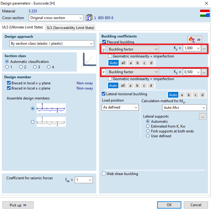
Using the SD1 (Steel design) module of AxisVM, we can choose to manually define the buckling coefficients for flexural buckling (with buckling factor, or buckling length).
When using asymetric cross sections for buckling check, it may occur, that the “Buckling factors” differs from what the buckling check uses, and what can be seen inside the detailed “Design calculation” report.
Example:
Cross section: L60x60x6.0
Manually defined buckling factor Ky=1
Manually defined buckling factor Kz=0.5
Applied “Ky” (KyD) and “Kz” (KzD)values in the “Detailed calculation” report:
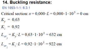
Explanation #
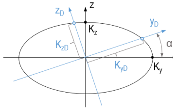
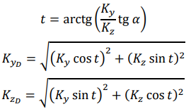
Buckling is interpreted along the principal axes. The “K” buckling factors that are needed to be considered during the calculation, are values in a rotated coordinate system, which can be assigned to the buckling around the principal axes.
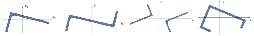
These modified “K” values are is determined by AxisVM as a result of elliptic interpolation. This type of interpolation can be interpreted as if the manually defined “K” values were measured on the local axes of the cross section (black axes on the picture below). An axissymmetric ellipse is then plotted, with the minor and major axis length set as the manually defined “K” values. Outline of the ellipse represents the possible values of the buckling factors for different alignments of the principal axes of the cross section.
By rotating the blue coordinate system with the cardinal direction, the values of the applied “KD” values can be read off at the intersection of the rotated coordinate axis with the ellipse.