AxisVM
  • Products
    • AXISVM
    • AXISVM X7 New Features
    • AXISVM Modules
    • Configurations
    • AXISVM Rapido
    • Free Products
    • HW/SW requirements
  • Downloads
    • Free Trial Versions
    • AXISVM Education Version
    • X7 Installation Package
    • Free Downloads
    • Latest Release Updates
    • Sentinel Driver
    • Applications & Plugins
  • Request for Quotation
  • References
    • AXISVM Testimonials
    • Customer Projects
    • Showcases
    • Recommendations
    • Art of Modeling
  • Support
    • Knowledge Base
    • Customer Support
    • Training Materials, Guides
    • Verification Examples
    • Patch Tests
    • HW/SW requirements
  • Contact
    • About us
    • Partners
  • HUN
  • DE

Latest articles

  • Increments and iterations
  • Convergence criterias
  • Modifying domains
  • Basics of vibration and seismic analysis
  • Grasshopper installation guide
  • Removal of unnecessary elements
  • Creation of a simple model using AxisVM COM server

Installation & Licencing

  • Setting up the COM server using Python
  • Setting up the COM server using Visual Studio
  • Error code 70 – Sentinel SuperPro-NET key
  • AxisVM-Autodesk Revit interface does not appear in Revit
  • Error when installing update package – errorcode 5
  • Error code -115
  • Save and restore settings

General

  • Parameter is incorrect – AxisVM does not start
  • Coordinate Systems
  • AXS files are not recognized by Windows 10
  • Access violation in module atio6axx.dll error message
  • Program can’t start due to spro_aex64.dll error message
  • Shear cross-section area Ay/Az

Modeling

  • Modifying domains
  • Removal of unnecessary elements
  • Creation of a simple model using AxisVM COM server
  • Compression or tension-only line elements
  • Scissor joint

Loads

  • Filter out critical load combinations
  • Auto-generated wind load differs from standard values
  • List of AxisVM messages – Loads
  • Number of automatic loadcombinations

Analysis & Results

  • Increments and iterations
  • Convergence of non linear calculations
  • Signs of internal forces
  • Newton-Raphson iteration for SDOF and MDOF systems
  • Convergence criterias
  • List of AxisVM messages – Analysis 
  • FOOTFALL ANALYSIS GUIDE
  • Simultaneous internal forces for connection design
  • The model contains singularities, unstable mode
  • Smoothing of results on beam and rib elements
  • Mathematical relative calculation errors
  • No convergence after nonlinear analysis

Vibration & Earthquake

  • Basics of vibration and seismic analysis
  • Modal response spectrum analysis mass participation can’t reach 90%

Design

  • Simply supported timber beam deflection check in module TD1
  • Buckling coefficients in Design calculation differs from Design parameters setting
  • List of AxisVM messages – RC design
  • X-LAM GUIDE – Structural Description of X-LAM Members
  • Critical results for concrete columns
  • AUTO Mcr GUIDE
  • APPLICATION OF STEEL CONNECTION (SC1 MODULE)
  • AutoNcr FLEXURAL BUCKLING COEFFICIENT CALCULATION (Guide)
  • Reducing the time of the design process

Reinforcement

  • Actual reinforcement rendering on the 3D model view

Documentation

  • Options for editing drawings of report maker

Elements

  • Compression or tension-only line elements

BIM Connections

  • Modeling doubly curved surfaces
  • Grasshopper installation guide
  • IFC connection

Mesh generation

  • Generating mesh for surface elements

AXISVM API

  • Grasshopper installation guide
  • Creation of a simple model using AxisVM COM server
  • Home
  • Latest articles
  • Modifying domains

Modifying domains

Table of Contents
  • Domain
  • Change domain contour
  • Hole
  • Cut a domain
  • Union of domains

In the AXISVM domains can be arbitrary spatial planar components. Their contour lines can be adjusted freely. The upcoming lines discuss that what possibilities are given to define or modify different types of shell elements.

Domain #

C:\6e09af94c4c4ce9d010ea2cd0bd12058

When defining a domain in the following window can the options be set. Here the thickness and eccentricity as geometrical properties and the material of course as a material property can be set.

The next setting which is quite important in calculation point of view is the applied finite element type. Basically there are three possibilities to set: membrane, plate and shell.

In the next picture inner force vectors of membrane elements are drawn with blue. As it can be seen clear, membranes can only take internal forces in the direction of their plane. The next, red vector set is ordered to plate elements. As it is consistent, plates can only take internal forces perpendicular to their plane. 

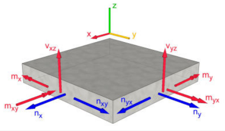
The third type of possible finite elements is the shell. In 3D models, all domains (planar components) should be defined as shell elements, since this elements can contain all internal forces. In spatial models, it is hardly possible to prevent that other (minimal) forces occur.

Change domain contour #

C:\7044b4ed2ea513602f6b9f46aea5cd06

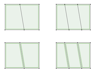
After activating the function “Change domain contour” the chosen domain outline will be selected. By selecting a new outline, the domain contour can be redefined. It should be noticed that the largest closed outline selected will be used as new domain contour. If the domain has to be downsized, the selection of the “excess” area needs to be removed.

C:\72690c455e8b1981a2e7246bec8952df

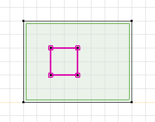
The command’s affect can be seen in the picture above. After selecting the domain and setting a spline which does not cut the contour of the selected area, it will result no affects. The next picture shows an example.

C:\beccd12b02bb633309343d9343e7cd44

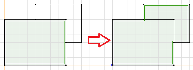
In this kind of formation the command is declined, it will not create an autonomic partial domain inside the original domain. This problem could be solved in the following way: select the spline and define it as a new domain. 

C:\a91d57e557bc2d826b91c64da4ba38fc

In this picture in can be properly seen that due to defining the smaller domain the area of the bigger domain has decreased.

Hole #

C:\d905dd3cbdd63d7b19c7c1b08f687f54

In the case when it is aimed to cut a partial area from the entire area, the cutting line can be given by the “Hole” option. Of coure, this opportunity also decreases the entire area and will be defined as a new domain type (hole) and will also get a serial number.

C:\ef00c7abb8f76b8ee698d110aa71756e

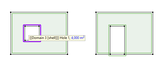
It is not possible to define a hole which extends over the original domain’s border. In this case the hole will fit to the edge of the domain. 
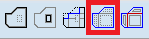
Cut a domain #

C:\cc93b9ba7dbabf3e26ddeb1ae40ffa2e

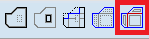
After activating the function “Cut a domain” one or more domain(s) can be selected. After confirming the selection with “OK” (selection toolbar) the cutting line(s) can be chosen. The cutting line has to run through the complete domain. 

C:\9af76705d9c4625353ee489ec6a142d8

When domains are cut, the properties of the original domains are used for all resulting parts.

Union of domains #

C:\be9f295884cd1db2b83fbb2c02c01908

After activating the function “Union of domains” several domains can be selected. By confirming the selection with “OK” (selection toolbar) the chosen domains are merged. 

If the properties of the domains are different, the domain that sets the properties of the new domain can be selected.

C:\e9fe5bcaec54620d65941661366d530b

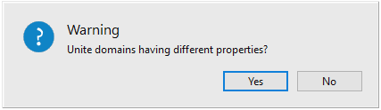
In case of this warning, by clicking “Yes” the domain can be selected, of which we want to keep the properties.

Source: http://www.ingware.com 

Still stuck? How can we help?

How can we help?

Basics of vibration and seismic analysisConvergence criterias
Table of Contents
  • Domain
  • Change domain contour
  • Hole
  • Cut a domain
  • Union of domains

CONTACT

InterCAD

Software Development Company
42 Rákóczi út, Floor V.
Budapest, H-1072
Hungary, EU

 
PHONE:    +36 (1) 322-9072
FAX:           +36 (1) 322-6668
SALES:      
SUPPORT:

NEWSLETTER

I consent to AxisVM sending me newsletters and informing me about product updates and discounts


    FOLLOW US

    Facebook-f Linkedin Youtube Instagram

    SOURCES OF PHOTOS USED ON THE WEBSITE >>

    IMPRESSUM >>

    © Copyright 2023 | Inter-CAD Kft. – All rights reserved

    We are using cookies to give you the best experience on our website.

    You can find out more about which cookies we are using or switch them off in settings.

    AxisVM
    Powered by  GDPR Cookie Compliance
    Privacy Overview

    This website uses cookies so that we can provide you with the best user experience possible. Cookie information is stored in your browser and performs functions such as recognising you when you return to our website and helping our team to understand which sections of the website you find most interesting and useful.

    Strictly Necessary Cookies

    Strictly Necessary Cookie should be enabled at all times so that we can save your preferences for cookie settings.

    If you disable this cookie, we will not be able to save your preferences. This means that every time you visit this website you will need to enable or disable cookies again.

    Cookie Policy

    More information about our Cookie Policy