In the following article, we will discuss calculating the instantaneous and final deformation of a simply supported timber beam considering the Eurocode standard. We compare and analyze the deflections resulting from the static analysis and deflections calculated by the TD1 module of the AXISVM software.

The calculation is carried out on a simply supported beam, hinged at both ends, which has a span of 5.50 m. The cross-section of the beam is 150×280 mm, the material quality is GL 28c, and the service class is 2.
The deflection calculation is presented for different load cases. For each load case, the permanent load is identical. In addition to its self-weight, a distributed line load of 1.10 kN/m acts as an additional permanent load on the beam.
Two load situations:
- Snow-loaded beam (e.g., in a rooftop slab): a snow load of 0.8 kN/m acts on the beam, the combination factors of the variable load to be considered: ψ0=0.5; ψ1=0.2; ψ2=0. In this case, no other simultaneous variable loads are applied.
- Slab beam load: two line loads of different intensities are working on the beam: 2 kN/m and 0.25 kN/m. The combination factors are the same for both loads: ψ0=0.7; ψ1=0.5; ψ2=0.3. The loads can act simultaneously.
Below we detail only the specifics of the deflection calculation and the assumptions used.
Static calculation #
The software considers the modulus of elasticity of timber elements with a reduced value when generating the stiffness matrix. Using the modified modulus of elasticity, the effect of creep is approximated in accordance with the specifications of the standard. The modulus of elasticity is obtained by dividing the mean value with E0, mean / (1+kdef) expression according to EN 1995-1-1, paragraph 2.3.2.2. For the beam in the current example, kdef is 0.8 (service class 2).
The TD1 module calculates the instantaneous and final deformation of the structure from the result of this static analysis.
The table below summarizes the results of the linear statics analysis and the calculated deflection values for each load cases. The deflection results of the critical load combinations are detailed later.
| Load case | Deflection results | |||
| Results of the linear static analysis | Results calculated by the TD1 module | |||
| Instantaneous deflection | Final deflection by approximate method | Final deflection by enhanced method | ||
| [mm] | [mm] | [mm] | [mm] | |
| G – beam self-weight | 1.08 | 0.60 | 1.08 | 1.08 |
| Permanent load | 6.88 | 3.82 | 6.88 | 6.88 |
| Live load – 1 | 12.51 | 6.95 | 12.51 | 8.61 |
| Live load – 2 | 1.56 | 0.87 | 1.56 | 1.08 |
| Snow load | 5.00 | 2.78 | 5.00 | 2.78 |
Instantaneous deformation #
The instantaneous deflection is calculated based on characteristic combination considering the following general formula. The deflection value from each load case is generated from the static results calculated by the reduced modulus of elasticity, dividing the deflection values by (1+kdef) (e.g., in the case of self-weight uinst,G,1=1.08/(1+0.80)=0.60 mm).
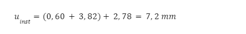
- For the beam loaded with snow, the maximum deflection is given by the combination [G+permanent load] {snow load}, i.e.:
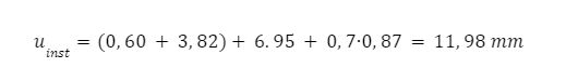
- For the intermediate floor’s slab beam, the maximum deflection is given by the combination [G+permanent load] {live load – 1} (0.7x live load – 2) /i.e.: leading live load – 1, accompanying live load – 2/:
Final deformation #
Calculating the final deflection value according to clause 2.2.3 of EN 1995-1-1 is mostly effective for manually calculating simple beams. However, in the case of complex spatial structures, the method leads to a rather complicated calculation. At least two independent static analyses would be necessary, one for short-term loads and one for long-term loads in the latter case considering the effect of creep. The calculation would be further complicated if elements with different creep properties and the stiffness of connecting elements and joints were considered.
The determination of deflection resulting from static analysis using the modulus of elasticity E0.mean / (1+kdef) can be considered a conservative method approximating the final deflection value from above. [Jack Porteous: Structural Timber Design to Eurocode 5]
To simplify calculation in TD1, two methods (approximate and enhanced) are provided to determine the final deflection value, from which the user can choose when defining the design member.
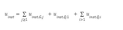
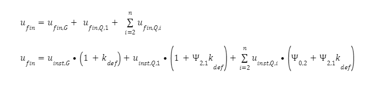
The final deflection is calculated based on the characteristic combination taking into account the following general formula:

Choosing the Approximate method, the program gives the final value of deflection based on the characteristic combination, essentially the results of the deflection (calculated with a reduced modulus of elasticity) are taken as the final value of deflection. (Due to the approximation, there will be creep deformation for any kind of variable load case. This includes, for example, a significant approximation compared to the calculation in point 2.2.3 where, for some standards, the ψ2 factor for snow loads is zero, and for example (1+ψ2 kdef) no creep is considered for snow load.)
- For the beam loaded with snow, the maximum deflection is given by the combination [G+permanent load] {snow load}, i.e.:

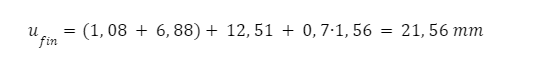
- For the intermediate floor’s slab beam, the maximum deflection is given by the combination [G+permanent load] {live load – 1} (0.7x live load – 2) /i.e.: leading live load – 1, accompanying live load – 2/:
In the Enhanced method, the module recalculates the deflection value from the results of the existing static analysis. It shall perform a correction calculation using existing static results, considering the short- and long-term effect of the loads. This is done without further static analysis using superposition on the existing deflection results for load cases, considering the combination factors (permanent, variable) for the type of load (belonging to the combination).
Therefore, the correction is only executed at the level of the design member level on the basis of the relative displacements. For this reason, this procedure can also be considered approximate, but in relation to the Conservative method, it gives a value closer to the calculation method described in the standard, giving the same result as the simplified calculation.
The program can perform the calculation for characteristic (automatic/manual) combinations or for individual load cases. In the case of individual combinations, ψ0 factor is taken from the combination factor (therefore, only individual combinations with a combination factor value of ≥ 0 or ≤ 1 can be considered). The ψ2 factors corresponding to the long-term proportion of loads are taken into account on the basis of the value corresponding to the load group of the load case included in that combination.
The deflection value of each load is summed up according to the following formula:
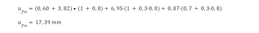
- For the beam loaded with snow, the maximum deflection is given by the combination [G+permanent load] {snow load}, i.e.:

- For the intermediate floor’s slab beam, the maximum deflection is given by the combination [G+permanent load] {live load – 1} (0.7x live load – 2) /i.e: leading live load – 1, simultaneous live load – 2 loads/:
Comments #
- A common question arises as to why the program uses the characteristic combination and not the quasi-permanent combination to calculate the final deflection.
The specification of the standard also takes into account the instantaneous deformation of loads when calculating the final deflection, not just the long-term effect. (Note: in some countries, the combination factor ψ2 of the snow load is declared as zero, which also means that the excess deformation due to snow load does not appear in the results of any of the quasi-constant combinations.)
AXISVM model file: download