AxisVM
  • Products
    • AXISVM
    • AXISVM X7 New Features
    • AXISVM Modules
    • Configurations
    • AXISVM Rapido
    • Free Products
    • HW/SW requirements
  • Downloads
    • Free Trial Versions
    • AXISVM Education Version
    • X7 Installation Package
    • Free Downloads
    • Latest Release Updates
    • Sentinel Driver
    • Applications & Plugins
  • Request for Quotation
  • References
    • AXISVM Testimonials
    • Customer Projects
    • Showcases
    • Recommendations
    • Art of Modeling
  • Support
    • Knowledge Base
    • Customer Support
    • Training Materials, Guides
    • Verification Examples
    • Patch Tests
    • HW/SW requirements
  • Contact
    • About us
    • Partners
  • HUN
  • DE

Latest articles

  • Increments and iterations
  • Convergence criterias
  • Modifying domains
  • Basics of vibration and seismic analysis
  • Grasshopper installation guide
  • Removal of unnecessary elements
  • Creation of a simple model using AxisVM COM server

Installation & Licencing

  • Setting up the COM server using Python
  • Setting up the COM server using Visual Studio
  • Error code 70 – Sentinel SuperPro-NET key
  • AxisVM-Autodesk Revit interface does not appear in Revit
  • Error when installing update package – errorcode 5
  • Error code -115
  • Save and restore settings

General

  • Parameter is incorrect – AxisVM does not start
  • Coordinate Systems
  • AXS files are not recognized by Windows 10
  • Access violation in module atio6axx.dll error message
  • Program can’t start due to spro_aex64.dll error message
  • Shear cross-section area Ay/Az

Modeling

  • Modifying domains
  • Removal of unnecessary elements
  • Creation of a simple model using AxisVM COM server
  • Compression or tension-only line elements
  • Scissor joint

Loads

  • Filter out critical load combinations
  • Auto-generated wind load differs from standard values
  • List of AxisVM messages – Loads
  • Number of automatic loadcombinations

Analysis & Results

  • Increments and iterations
  • Convergence of non linear calculations
  • Signs of internal forces
  • Newton-Raphson iteration for SDOF and MDOF systems
  • Convergence criterias
  • List of AxisVM messages – Analysis 
  • FOOTFALL ANALYSIS GUIDE
  • Simultaneous internal forces for connection design
  • The model contains singularities, unstable mode
  • Smoothing of results on beam and rib elements
  • Mathematical relative calculation errors
  • No convergence after nonlinear analysis

Vibration & Earthquake

  • Basics of vibration and seismic analysis
  • Modal response spectrum analysis mass participation can’t reach 90%

Design

  • Simply supported timber beam deflection check in module TD1
  • Buckling coefficients in Design calculation differs from Design parameters setting
  • List of AxisVM messages – RC design
  • X-LAM GUIDE – Structural Description of X-LAM Members
  • Critical results for concrete columns
  • AUTO Mcr GUIDE
  • APPLICATION OF STEEL CONNECTION (SC1 MODULE)
  • AutoNcr FLEXURAL BUCKLING COEFFICIENT CALCULATION (Guide)
  • Reducing the time of the design process

Reinforcement

  • Actual reinforcement rendering on the 3D model view

Documentation

  • Options for editing drawings of report maker

Elements

  • Compression or tension-only line elements

BIM Connections

  • Modeling doubly curved surfaces
  • Grasshopper installation guide
  • IFC connection

Mesh generation

  • Generating mesh for surface elements

AXISVM API

  • Grasshopper installation guide
  • Creation of a simple model using AxisVM COM server
  • Home
  • Mesh generation
  • Generating mesh for surface elements

Generating mesh for surface elements

Table of Contents
  • Mesh type and element size
  • Empirical values for element size
  • Mesh adjustments

Mesh type and element size #

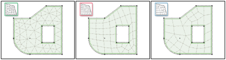
Triangular meshes are flexible in terms of geometry (e.g. rounded, pitched-in corners) and in general produce a regular mesh. Triangular elements are suitable for RC constructions, since their components usually feature a relativeley low slenderness. 

Quadrilateral meshes are less flexible, but tend to produce better results for thin surfaces (high slenderness), like steel plates. 

Combined meshes try to combine the advantages of triangular and quadrilateral meshes. But in many cases they produce an irregular mesh. Combined meshes are recommended for thin surfaces with complex geometry.

Empirical values for element size #

For buildings in concrete and masonry, triangular meshes with the following element sizes have proven to serve the purpose in many cases. 

  • Floors 1,50 … 2,00 m 
  • Walls 1,00 … 1,50 m 

For very narrow components it can be of advantage to choose a smaller element size. If possible it is not recommended to use element sizes below 0.50 m. Depending on the calculation, individual domains can be meshed with considerably greater element sizes (e.g. floors in seismic calculations).

Mesh adjustments #

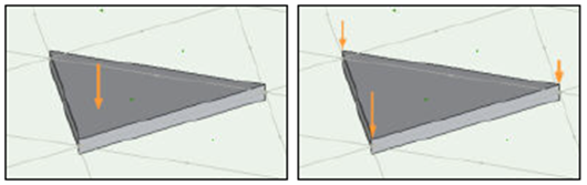
The mesh adjustments (“fit mesh to loads”, “adjust mesh to column head”) forces mesh nodes an lines at defined places. 

  • Load application point for nodal loads (mesh node) 
  • Load application line for line loads (mesh line) 
  • Contour of load application area for surface loads (mesh line) 
  • Corners of column cross-sections (mesh node)

The fitting of the mesh to loads is meant to guarantee a most accurate consideration of the loads. If a load acts on a point inside an element, it is spread out for calculation purposes to the nearest nodes and is (taken literally) not a point load any more, but a ‘surface load’ over a small area.

If the mesh is adjusted to column heads, the elastic peaks in the moment distribution can me smoothed out automatically. To do so, it is necessary to introduce a mesh node at the corners of the column cross-section. This leads to a lot of nodes closely together for round columns, which is not ideal. In extreme cases the mesh generation can be impeded by this situation.

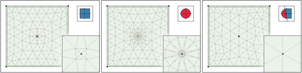
To use the mesh adjustment for thin walled cross-sections (e.g. steel profiles) and still get a good mesh, the corners of the convex contour of the cross-section are used to adjust the mesh.

Source: http://www.ingware.com 

Still stuck? How can we help?

How can we help?

Table of Contents
  • Mesh type and element size
  • Empirical values for element size
  • Mesh adjustments

CONTACT

InterCAD

Software Development Company
42 Rákóczi út, Floor V.
Budapest, H-1072
Hungary, EU

 
PHONE:    +36 (1) 322-9072
FAX:           +36 (1) 322-6668
SALES:      
SUPPORT:

NEWSLETTER

I consent to AxisVM sending me newsletters and informing me about product updates and discounts


    FOLLOW US

    Facebook-f Linkedin Youtube Instagram

    SOURCES OF PHOTOS USED ON THE WEBSITE >>

    IMPRESSUM >>

    © Copyright 2023 | Inter-CAD Kft. – All rights reserved

    We are using cookies to give you the best experience on our website.

    You can find out more about which cookies we are using or switch them off in settings.

    AxisVM
    Powered by  GDPR Cookie Compliance
    Privacy Overview

    This website uses cookies so that we can provide you with the best user experience possible. Cookie information is stored in your browser and performs functions such as recognising you when you return to our website and helping our team to understand which sections of the website you find most interesting and useful.

    Strictly Necessary Cookies

    Strictly Necessary Cookie should be enabled at all times so that we can save your preferences for cookie settings.

    If you disable this cookie, we will not be able to save your preferences. This means that every time you visit this website you will need to enable or disable cookies again.

    Cookie Policy

    More information about our Cookie Policy