- APPLICATION OF STEEL CONNECTION (SC1) MODUL
- Type of joints
- Column-beam semi-rigid connection
- Girder-beam semi-rigid connection
- Column-beam nominally pinned connection
- Girder-beam nominally pinned connection
- Column-beam endplate connection
- Beam-beam endplate connection
- Beam splice
- Column-base connection
- Pipe splice connection
- Gusset plate (single truss) connection
- Tube node connection
- Girder-beam rigid connection
- Knee welded connection
- STANDALONE STEEL CONNECTION
APPLICATION OF STEEL CONNECTION (SC1) MODUL #
In general about the module #
Verification of steel connection | The SC1 module is suited for examination of steel connection. The steel connections have to be accordance with standard requirements. The component method of standard is applied in the module, it means that the resistance of a joint should be determined on the basis of the resistances of its basic components. | ||||
Standards | The following standards are used in the module to verify the steel connection: EN 1993-1-1 (2005): Eurocode 3: Design of steel structures - Part 1-1: General rules and rules for buildings EN 1993-1-8 (2012): Eurocode 3: Design of steel structures - Part 1-8: Design of joints Furthermore the standards referred to in these standards. | ||||
Types of joints | a) Column – Beam (semi-rigid) | b) Column – Beam (nominally pinned) | |||
c) Girder – beam (semi-rigid) | d) Girder – Beam (nominally pinned) | ||||
e) Beam – Beam (Endplate) | f) Beam – Column (Endplate) | ||||
g) Beam splice | h) Column-Base | ||||
i) Pipe splice | j) Gusset plate (single truss) | k) Tube node | |||
l) Grider-beam rigid connection | m) Knee welded connection | ||||
☞ | The limitations and the scope of module are detailed by each type of joints (2. Type of joints). | ||||

Configuration of the joint #
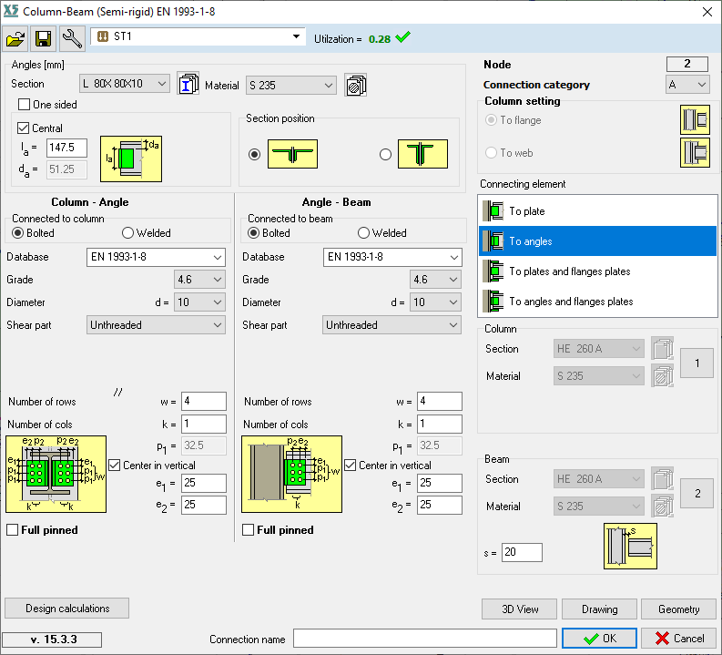
Getting started | Select the required type of joints and then select the connecting members of the joint. Selection is considered when the OK button is pressed. After this the main dialog window appears. The main dialog window depends on the type of joint. |
Multiselection | Defining the same joint for multiply nodes is possible with selecting more structural members. In case of this the program check the joint for common internal forces. The multiselection feature finds all common nodes automatically taking into account only the valid nodes for the given connection (for beam-beam it will not take into account nodes between beam-column). SC1 looks at the end nodes of each selected beam. |
Configuration | The properties, as cross-section and material, of the members, which take part in the joint cannot be modified. In the main window the type of and the geometrical and material properties of the components can be set. In some cases the proportions on multiple tabs can be set. The default settings always satisfy the geometric requirements, but not certainly the ultimate limit state. |
Bolted connection | In case of bolted connection the arrangement of the bolts have to be set based on the figure in the dialog window. The additional parameters can be set or modified, as follow:
|
Welded connection | In case of welded connection the type of welds (fillet weld, butt weld), and the length of them have to be defined, if it is necessary. |
Starting dialog window (example) képcsere |
File menu #
A previously saved connection can be opened by Open. In this case just the same type of connection can be opened. All of the settings are loaded, even the cross-section. After opening always necessary check the configuration of the connection and the calculation. Usually this menu is used in Standalone mode. |

Save #
Applying Save menu the geometric and other settings can be saved and it can be opened later. This option save each connection type with different extensions. Otherwise on each node the defined/designed connection is saved to axs model file. This feature is automatic and available when the dialog window is closed by OK button after design. The designed connections can be managed via Steel connection manager. See… 1.5 Steel connection management If a previously saved connection is opened and in the meantime one of the connected member is changed the calculation cannot be carried out. It means, have to be careful if you open connection from file. | |

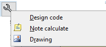
Settings #
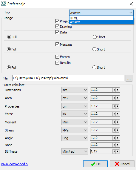
In Settings menu the following setup options can be found: Design code The standard cannot be changed. The safety factors can be modified manually. Note calculate The report can be detailed or short version, here can be set it. The type of the report as HTML or AxisVM also can be select. The place of report on disc and the units can be changed. Drawing The colours in case of drawing and 3D view can be modified, clicking on the colour it can be changed. | |
Exit #
Exit option in file menu is out of work. Exit is possible in the following ways:
|
Checking the design joint #
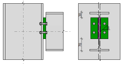
3D View | Press 3D view button and in a new window the connection can be seen, and it can be rotated. The settings can be checked with this option. The window has to be closed, without this cannot continue the verifying. |
Drawing | Press Drawing button and in a new window various drawings of the joint are displayed. Do not have to close the window, if some parameters are changed then press Drawing button again, the window will be updated. |
Geometry | The connection should satisfy geometric requirements specified by standard. The module checks them and shows OK if everything are in accordance with requirements. Otherwise the inadequate parameters are detailed. It is important to note, that the program calculates even if the connection is not appropriate geometrically. |
The procedure of calculation #
Calculations | The program calculates automatically the utilization for the set load case, load combination, envelope, criticals. If we have changed the parameters we can recalculate the results by clicking the Calculation button in the upper right corner of the dialog. We can check the details of the calculation by clicking the Design calculations button. See… 1.4.1 Detailed report |
Analyses | The SC1 module calculates the resistances of the connection and the utilization associated with them. In the following some ultimate resistances are listed. |
Resistance of bolts | In case of bolted connection depends on the type of the stresses the following resistances are calculated::
|

Resistance of welds | Directional method (Section 4.5.3.2 in EN 1993-1-8) is used to checking the welded connections. |
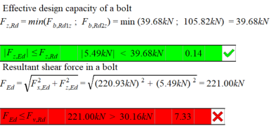
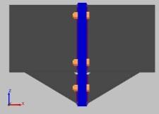
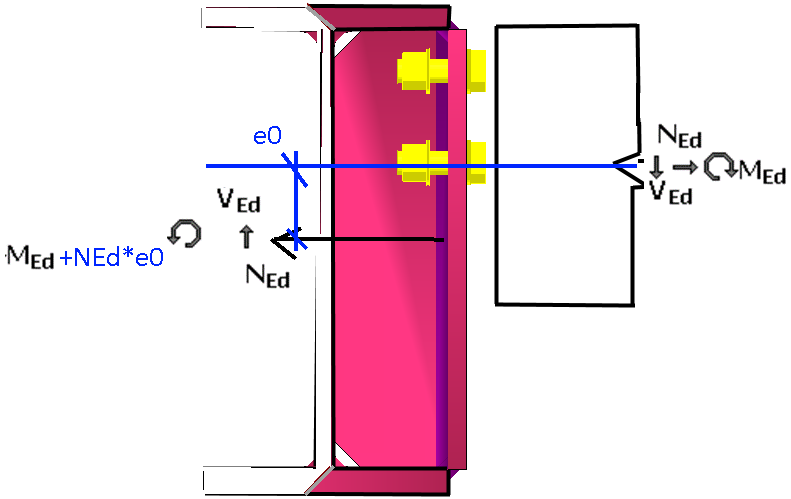
Internal forces and moments képcsere | The program always calculates the internal forces of the most utilized bolt.
The eccentricity due to the character of the connection is taken into account through the design force generated by bending moment. |


Verifying bolts |
|
Detailed report #
In the Note calculate menu the type of the report can be selected, as HTML or AXISVM. | |
Képcsere (+stiffness) | |
Clicking on the Design calculations button, detailed report displays about the connection, regardless of the type of report: | |
The report contains the following:
The results are determined in case of ultimate limit sates and serviceability case depends on the connection type. The program carries out the verifying even if the internal force is zero. The results are shown by highlighting. Green colour means it is passed, and the red means not passed. | |
In case of HTML report type an IconBar can be found at the top of the window, which contains the print preview and type of the exporter software (MS Word). The latter can be used for exporting. | |
The AxisVM report type means the same format as the original report in AxisVM program. The report of the designed connection can be added to the full AxisVM report. It has to be noted, if the type of the report is AxisVM, the report is not updated if something is changed in the model. Therefore save the report at the last step. | |
Képcsere | |


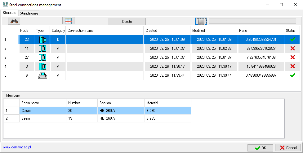
Steel connection management #
The steel connection management summarizes the designed connections. There is a possibility to delete connections. If something is changed in the model, the Ratio and the Status will be blank. The calculation can be easily done again by clicking the calculator icon. Double click on a row and the main window of the connection design appears. The table contains the following:
| |
The node associated with the selected line can be displayed with the binoculars icon. |


Type of joints #
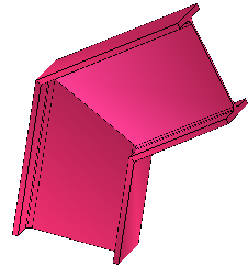
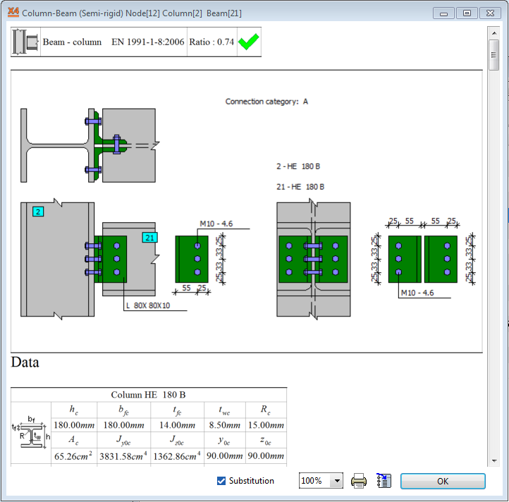
Column-beam semi-rigid connection #
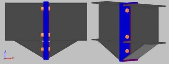
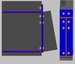
This type of joint is suitable for rectangular column-beam connection. The angle cannot be different from perpendicular. The place of connection (on the flange or web of the column) is automatically detected. There is a full pinned option, where the internal forces from the moments are neglected. Just axial and shear forces are transmitted. The applicable cross-sections: Column: I-, H- shapes, RHS (Box shape) Beam: I-, H-shapes | |
☞ | The rotational stiffness of connection and the value of Sj,ini are not determined. The moment resistance is not determined, but the internal forces from the bending moment are taken into account in the calculation. |
☞ | The program does not check the fin plate and the angle member for bending moment and shear force. The checking of the beam web panel in shear have to be carried out by the user. |
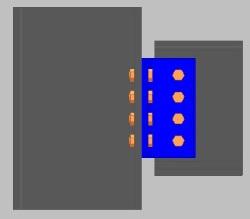
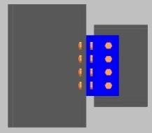
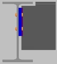
Fin plate connection Optional one-sided fin plate, welded or bolted connection. Moment from the eccentricity of the bolt/weld arrangement is taken into account. | |
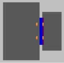
Double (angle) web cleats connection Optional one angle web cleat, not necessary use double angle. In both cases of column-angle and angle-beam connection the eccentricity is taken into account. | |
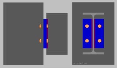
Fin plate connection and flanges plates There is on option to apply stiffener for column web, the parameter of the stiffener can be specified on a separate tab. The program divides the axial forces into three parts proportionally according to the areas of flanges and web. |


Web cleat connection with flange plate Specify the connection and the verifying of the connection are carried out in the same way as fin plate connection and flanges plates. | |

Girder-beam semi-rigid connection #
The verifying is similar to column-beam semi-rigid connection. There is no option to connect the flanges directly to the girder. The default setting is a flush girder-beam connection, but it can be modified by changing the parameters. |
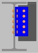
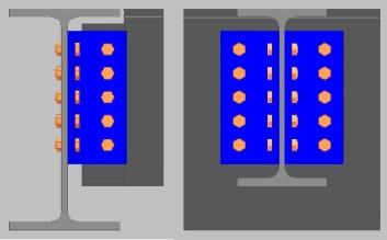
Fin plate connection There is one- or double sided fin plates option. | |
Web (angle) cleat connection There is one- or double web cleats option. | |
Brace plate (stiffener) connection Only one sided plate can be used which can be bolted or welded connection. |


Column-beam nominally pinned connection #
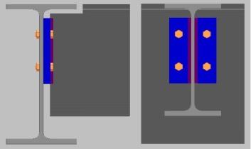
This is a header plate connection, actually a short endplate is used. In case of semi-rigid connections there is a check box for nominally pinned connection where fin plate or web cleat is used. | |
☞ | The program does not check the fin plate and the angle member for bending moment and shear force. The checking of the beam in shear have to be carried out by the user. |
Girder-beam nominally pinned connection #
This is a header plate connection, actually a short endplate is used. In case of semi-rigid connections there a check box for nominally pinned connection where fin plate or web cleat is used. | |
☞ | The program does not check the fin plate and the angle member for bending moment and shear force. The checking of the beam in shear have to be carried out by the user. |
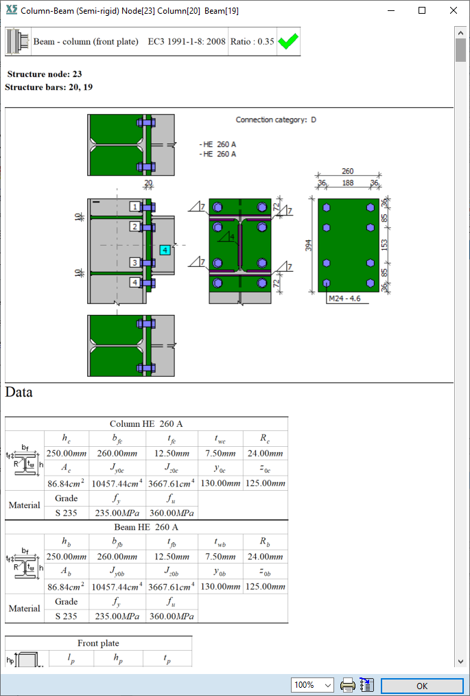
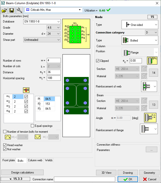
Column-beam endplate connection #
The column and the beam have to be selected to apply this type of connection. This type of connection is valid only for uniplanar connection. It is not suited for checking spatial connections. The checking procedure is the same as in EN 1993-1-8 is specified. The design moment resistance, rotational stiffness and rotational capacity are determined based on basic components of joints. The applicable shapes: I-, H-shapes and variable I-shapes. Wedged I-shape defined in cross-section editor is not applicable. In the module there is an option to select and set haunched beam. There is no flange cleat, just haunched beam or stiffener plate. In the main window the following settings can be set:
On various tab can be set the parameters of bolts, plates and etc. On the Bolts tab beyond basic properties of the bolts, specifications are found:
It is important to check the changes with Drawing or 3D View. See… 1.3 Checking the design joint The checking procedure can be followed in the report. The moment resistance of the joint is determined according to Tables 6.1 and 6.2 of EN 1993-1-8. The directional method is used, the flange welds need to be designed to transmit part of axial, shear forces and bending moment. The web welds need to transmit part of shear force and bending moment. The rotational stiffness is determined based on Section 6.3 of EN 1993-1-8, it is detailed in report. More information about the report in Section 1.4.1 Detailed report are founded. If an endplate is necessary for the joint, but the joint does not transmit moment, this kind of joint have to use. | |
Beam-beam endplate connection #
The two connected beam have to be selected for the calculation. Based on the relevant components, the moment resistance is determined the same way as by column-beam endplate connection. If the axial force exceeds the 5% of design resistance Npl,Rd the resistance of the joint should be satisfied using interaction formulae. Only I-, H- shape can be used. The following properties can be set:
To set and verify the joint is the same as in case of column-beam endplate connection. The report contains the detailed calculation. | |
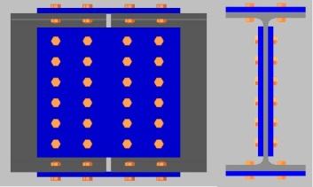
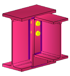
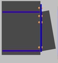
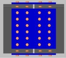
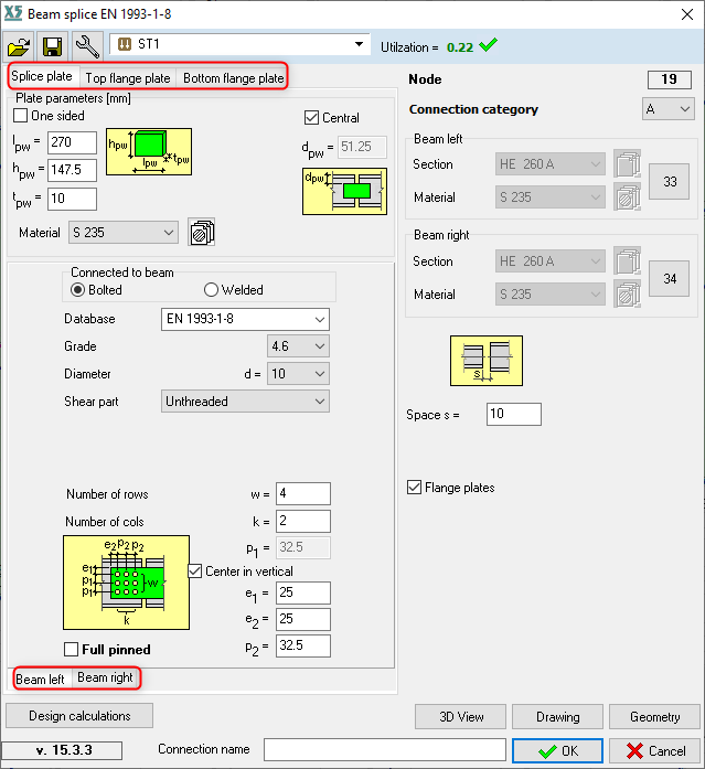
Beam splice #
2.7_1.jpg | The resistance of the connection should be satisfied the internal forces. Both sides (beam left, beam right) of the connection have to be specified. Among others the following properties can be set:
Inner bolted cover plates are available. |
☞ | The web plates in bending have to be checked by the user own. Please check the report. |
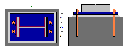
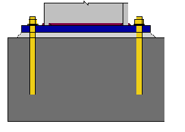
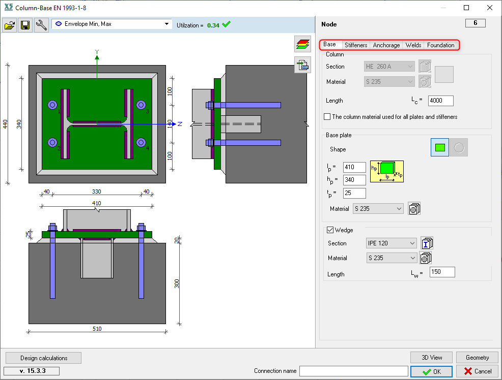
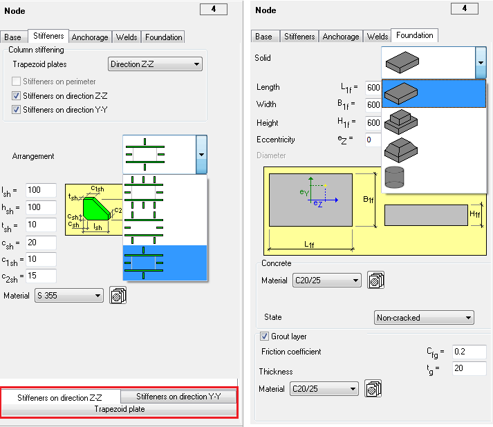
Column-base connection #
The column and the node have to be selected for column-base connection. On the node have to be defined a support, otherwise it is invalid. The column have to be vertical, parallel to z-axis. The checking procedure and the resistance components are the same as the standard (EN 1993-1-8) required. Applicable shapes:
The following properties can be set:
The stiffeners and the geometrical properties of them can be set. Optional stiffeners:
The type and properties of the anchorage can be set on Anchorage tab. The defined pad footing on R.C. design tab is not imported to Foundation. On Foundation tab have to set the parameters by the user. | |
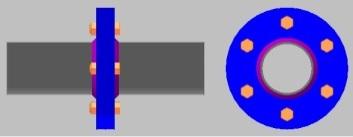
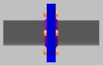
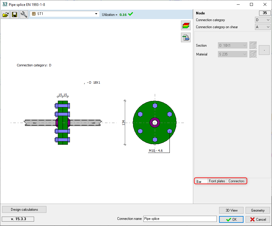
Pipe splice connection #
The calculation method is the same as in CEDICT (http://www.cidect.org/design-guides/) The resistance of the joint is carried out based on a similar conception as the T-stub element analysis in EN 1993-1-8. The following component resistances are taken into account, in the parentheses there is the corresponding internal force:
CHS (pipe) member:
RHS (box shape) member:
The selected pipes/boxes have to have the same cross-section. | |
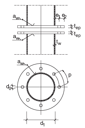
Geometrical requirements of T-stub |
| ||||||||
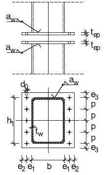
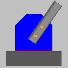
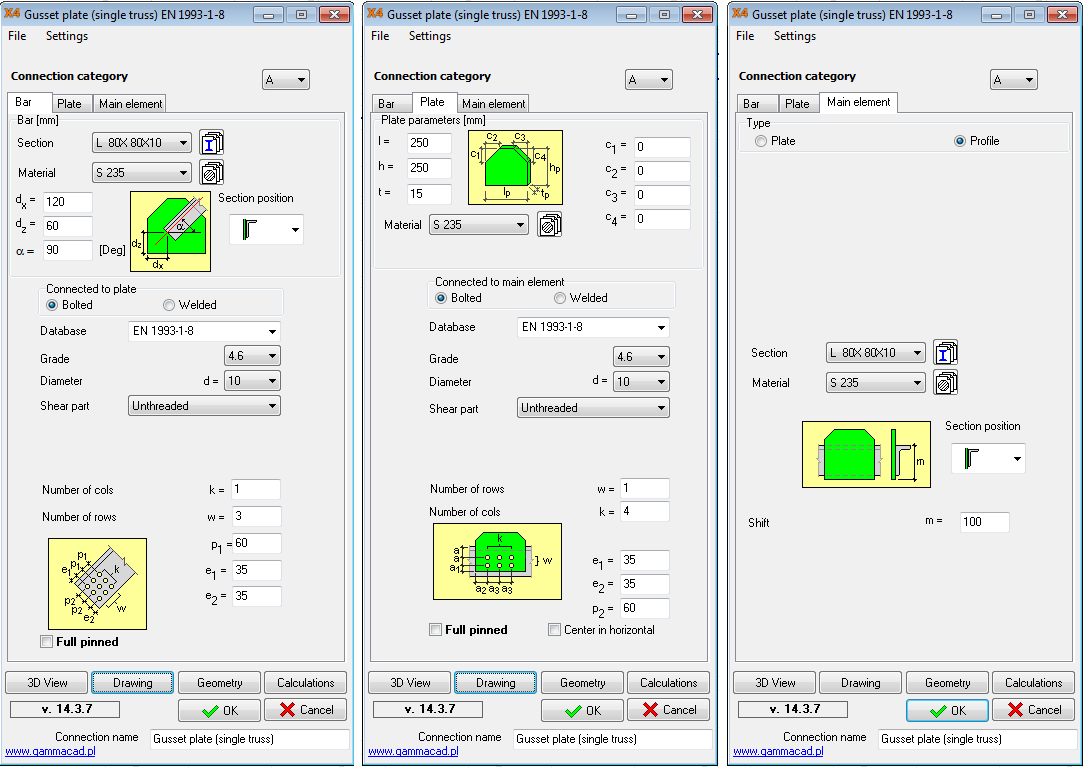
Gusset plate (single truss) connection #
The geometrical arrangement have to be set by user. The main element is the chord member of truss or a column. In addition plate element can be set as main element on Main element tab. By default settings the connecting members are perpendicular to each other. It is important to check the geometry by using Drawing and/or 3D Views. Verifying of:
|

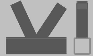
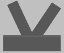
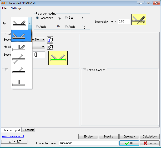
Tube node connection #
The members, are involved in the connection, should be selected. If just one bracing member is selected in a K-joint, the program will calculate as the joint would be Y-joint. Just uniplanar connection can be verified, if the connection is spatial/3D or there are more than two bracing members, the user should be calculate manually. There are various types of joints in lattice girders. User can applying different leading parameter and hereby change the geometry of the joint. Leading parameters:
Stiffener can be used on chord member if it is necessary. | |
The geometrical parameters are verified based on Section 8.7 of EN 1993-1-8. Using Geometry button, the satisfaction of the geometrical requirements can be checked. Some ultimate failure mode can be avoid by compliance with geometrical criterions. The program checks the following ultimate failure modes if it relevant to the type of joint and to applied cross-sections:
|
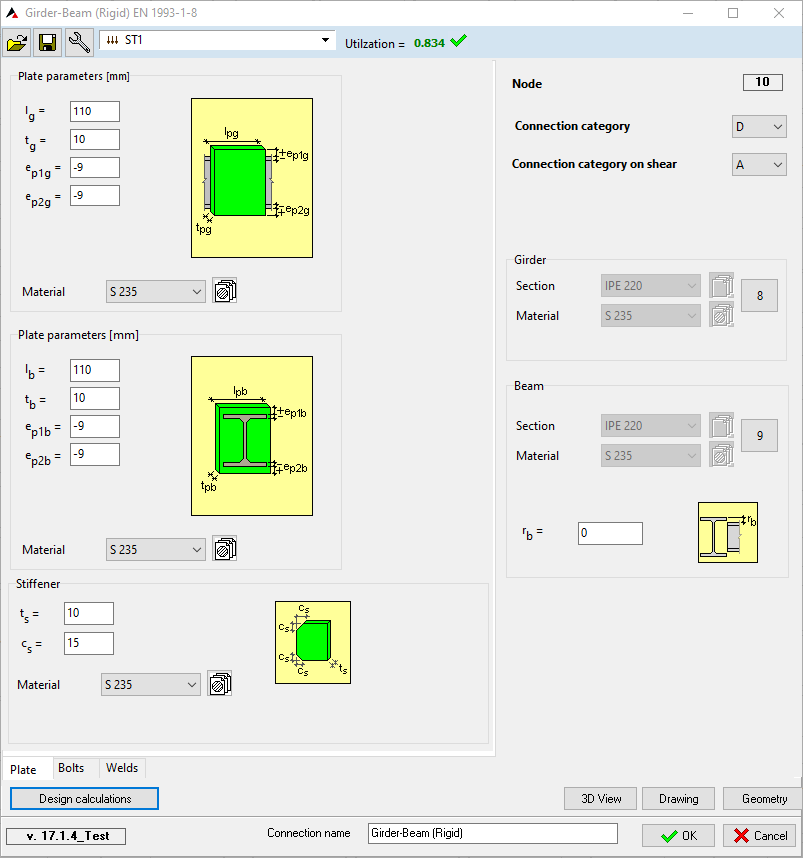
Girder-beam rigid connection #
Members are involved in the connection should be selected with their common node. User can select left or right part of a girder, but can’t select both of them if they are not assmebled to one member. Allowable sections are I and C shapes for grider, I and RHS for beam. Calculations are performed for both sides. The main side of connection is the beam side and the second is girder side. The internal forces of the girder side are reduced to virtual centroid point of girder. Verifying of:
| |
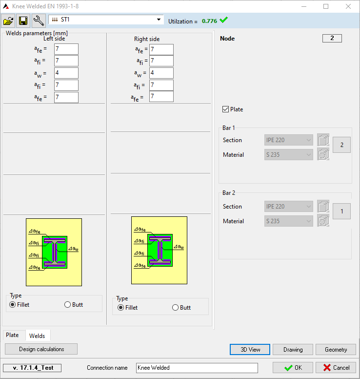
Knee welded connection #
Members are involved in the connection should be selected with their common node. The program checks the local coordinate systems of members, Y local axes should be parallel. Allowable cross sections are I, RHS, CHS, hauched I and double haunched I shapes. Calculations are performed for both sides. | |
STANDALONE STEEL CONNECTION #

Standalone steel connection plugin is available in AxisVM program. It can be used independently. The previously detailed types of connections are available through this. | |
There is no need to be selected nodes and elements. The elements can be selected from cross-section library or from combo-box, which contains the already selected cross-section in the model. The shapes of the applicable cross-sections are limited according to the type of joint. In the first step have to be set the elements and the geometry of the connection. Press button Calculation and the following dialog window appears: The internal forces have to be added in this dialog window. Results cannot be imported from model file. On the left side can be set the current highlighted internal forces. Press button OK and the calculation is carried out for the highlighted case. |
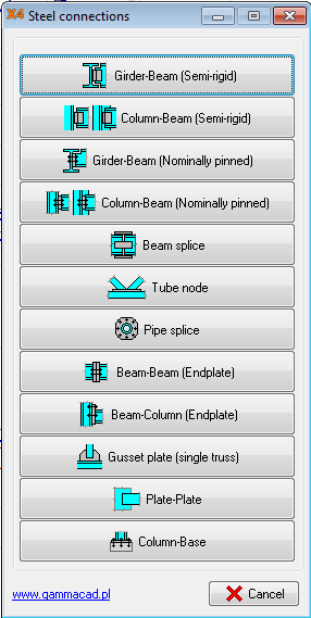
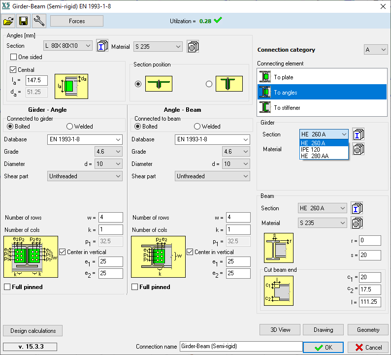
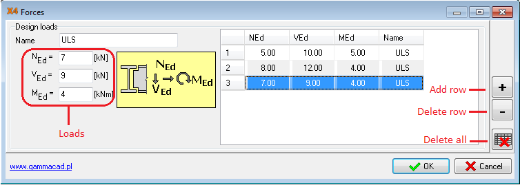
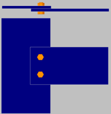
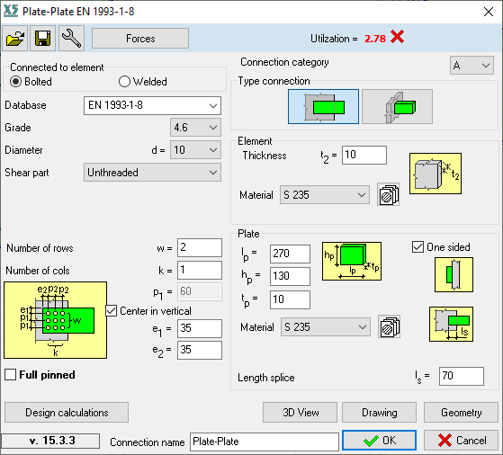
Plate-plate connection #
The plate-plate connection is available in standalone mode. Simply plate to plate bolted or welded connection can be verified. The plates may be perpendicular or parallel to each other. The set of the connection and the calculation method are the same as previous connections. |
NOTES