Introduction #
The WIND module enables users to determine wind loads on structures that fall outside the scope of the standard.
For typical roof types, including flat, monopitch, duopitch, and hip roofs, the standard provides pressure coefficients for the building’s principal directions. If the geometry deviates from these typical forms, if environmental influences on the airflow must be considered, or if wind loads are needed in more than the four main directions, a detailed analysis becomes necessary—this is where the WIND module supports the designer.
Overview of the WIND Module #
The users can either specify a custom wind profile or apply one defined by standards such as EN 1991-1-4 or SIA 261.
The users can consider the surrounding objects that affect the airflow and contribute to wind loads.
For certain structures, it may be necessary to evaluate the wind load not only in the four principal perpendicular directions but also in oblique directions. CFD simulation’s robust capabilities make this possible.
What’s new in X8 #
Starting from version X8, the module also supports the British standard.
Improved stability and faster performance through mesh quality analysis.
New result components! The wall shear stress can be displayed on the structure’s surface. The dimensionless wall distance is visible on the surface of the structure, allowing users to evaluate the mesh quality, particularly the level of refinement along the wall.
The module reviews the simulation results to assess both the quality of the calculations and the reliability of the pressure field.
Practical examples #
Hospital, Chêne-Bougeries, Switzerland #
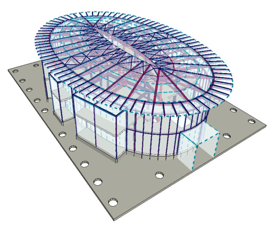
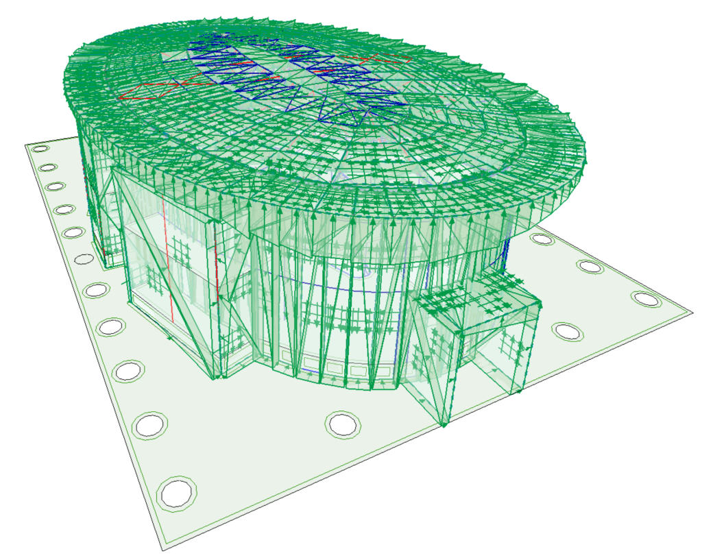
The structure is oval with a slightly curved roof. Façade elements extending from the elliptical layout in the floor plan influence the airflow around the building.
► The façade is modelled with load panels.
Due to the complex geometry, standardized methods for determining wind loads are either not applicable or require significant approximations. Furthermore, the complexity of the geometry suggests that examining wind loads in just four directions may be inadequate. The AXISVM WIND module also assists the user in this regard, enabling the calculation of wind pressures and loads in any direction.
The software uses streamlines to make the airflow around the structure visible:
For the structural engineer, the most important output is the pressure field, which the software displays on the envelope surface of the structure:

From the reduction of the pressure field, the software generates surface loads:
Apartment building, Sotrac, Barcelona, Spain #
This is a multi-storey CLT building in Barcelona. While the structure is not geometrically complex, its shape does not conform to standard forms.
Another challenge was the user’s intention to consider the influence of the urban built environment on airflow and wind load. This is also made possible by the WIND module.
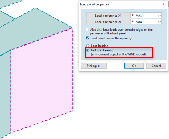
► Environmental objects and adjacent buildings can be modeled as ‘Non load bearing’ load panels. This option ensures that the software does not assign loads to these panels.
Streamlines around the building and its surroundings:
Timber lookout tower, diploma project #
The 20-meter-tall lookout tower is topped with a spherical cap measuring 7 meters in diameter. Inside, a spiral staircase with a 4-meter diameter forms the main stair structure:
The difficulty of the task arises from the structure being only partially enclosed. A dense wooden cladding that weaves through the load-bearing structure protects the interior space from the wind. As a result, the airflow slows down significantly, thereby increasing the wind load on the structure.
Classical methods for determining wind load require significant approximations and conservative assumptions, often neglecting the permeability of the cladding.
► The AXISVM WIND module allows for the analysis of open structures as well!
Streamlines entering the structure:
The software generates line loads on the rods by integrating the pressure field:
► In the case of truss elements, the wind pressures acting on the members are represented by concentrated forces applied at the member endpoints.
Integration with other AXISVM modules #
The WIND module generates loads based on the resulting wind pressure and shear stress. Since the simulation assumes steady-state flow, one static load case is generated for each wind direction. These load cases can be considered in linear and nonlinear static analyses, as well as in buckling analyses.
Tips for using the module efficiently #
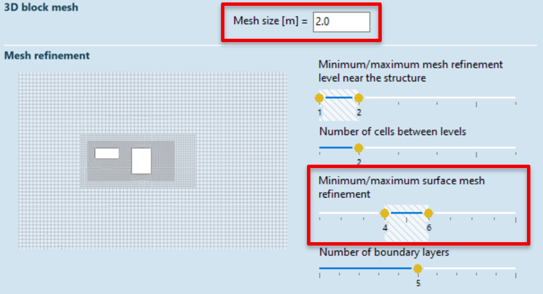
► The meshing algorithm refines the block mesh size n times in the vicinity of the structure. This implies that the smallest thickness the meshing algorithm can still enclose is mesh size/2n. The value of n corresponds to the ‘Minimum/maximum surface mesh refinement’ setting. Therefore, if we want to mesh a 10 cm thick balcony slab with a block mesh size of 2 meters, n must be at least 5, since in that case 2 m / 25 = 0.0625 m. If the refinement level is lower than this, the mesh will not represent the geometry adequately.
► Elements that do not have a considerable impact on the wind load should be excluded from the simulation. For instance, a bracing cable with a small diameter generally has minimal impact on the wind load; however, accounting for it can considerably increase the complexity of the simulation.
► First, analyze the structure using a coarse mesh, then perform the simulation with a refined, more accurate mesh.
Summary #
Experience the power of fluid dynamics—without ever leaving your comfort zone! Contemporary architectural solutions often result in structures for which no pressure coefficients are available. The CFD simulation module integrated into AXISVM enables the determination of wind loads even for general or unconventional geometries.
The module is capable of handling both enclosed and open structures. The wind tunnel simulation can account for both surface elements, including load panels and line elements. The software reduces the pressure field and wall shear stress to these elements, ensuring that the force system obtained from the CFD simulation is equivalent to the one used in the structural analysis.


